|
|
Kezdőlap-Home
Page |
||||||||||||||||||||||||||||||||||||||||||||||
|
II. évfolyam 3. szám 2001. július [HUN] - Magyar cikk
|
Dynamic Simulation of the Movement of Ceramic Particles in front of an Approaching Solidification Front Á.Borsik LIMOS R&D, Department of Physical Chemistry
1. Introduction The properties of particle reinforced metal matrix composites (MMCs) are determined by their microstructure, mainly by the position of the particles in the matrix. The particles will be concentrated at the grain boundaries if they are “pushed” by the moving solidification front of the growing crystal, what is an undesired event during processing of MMCs. This phenomenon can results many adverse effects mainly to the mechanical properties of MMCs. The main theoretical contributions to this so-called pushing/engulfment problem are listed in chronological order [1-47] (see also reviews [48-55]). According to the majority of models the main pushing force between the solidification front and the particle has an interfacial origin [1-3, 5-8, 10-18, 23-28, 30-39, 41-47], although other phenomena, such as the change of front curvature due to different heat conductivities of the metal and the particle [4, 9, 29], solutal field [7, 8, 12, 19-21, 28] or even convection in the liquid metal [22, 27, 41] can also lead to an inhomogenous distribution of the particles. Based on literature data [1-55] the following forces should be taken into account acting on a particle in the vicinity of a growing solidification front (forces are called ‘attractive’ or ‘repulsive’ relative to the solidification front):
The shape of the interface is generally not planar. The shape of the interface (and the particle) will influence the values of all the forces (except of the gravity force), but will not change their direction. In case of pushing interfacial force, the particle can be engulfed by the front above a certain critical interface velocity, ensuring high enough drag force, pushing the particle into the solidification front. The theoretical determination of the ‘critical interface velocity’ and the ‘critical interface distance’, when the pushing-engulfment transition (PET) takes place is the major task. The majority of models analyze the above listed forces in steady-state, neglecting dynamic effects. However, Stefanescu et al. in a series of papers [33, 36, 38, 44] suggested that dynamic effects lead to PET, although no dynamic analysis was performed in papers [33, 36, 38, 44] at all. In the recent paper of Stefanescu et al [45] on the dynamic s of the process, indeed some difference between the steady state and the dynamic solution of the PET has been found. However, Stefanescu et al uses quite different set of equations from those what will be used in this paper (for the discussion see [37, 38,, 43-44]. The goal of this paper is to build a dynamic model in order to find the dynamic conditions of PET and to check how much it is different from the steady-state solution for PET. The dynamic model has been created to study the dynamics of the process while the front is approaching the particle and the particle accelerates from its starting position to its steady state motion, i.e. moving together with the front. The present paper will describe the first two simplest generations of the series of our dynamic simulation models. For simplicity only the pushing interfacial force and the drag forces will be taken into account. In the first generation of our model the simplified planar interface, while in the second generation of the model the more complex curved interface will be taken into account. In the second generation of the model the critical interface velocity and critical separation can be obtained, as well.
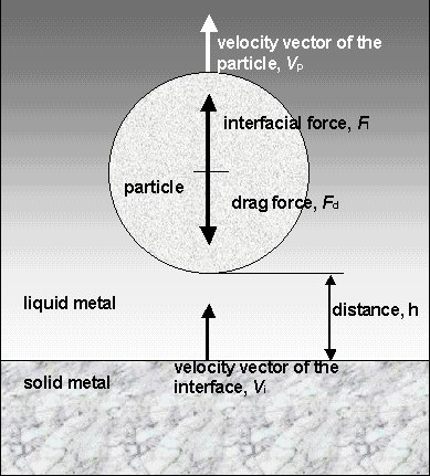
2. Description of our first generation model and results Let us consider a planar solidification front moving with a steady state velocity of vi, towards a single spherical particle of radius R (see Fig.1). Let h be the distance between the particle and the front.
Fig. 1. A spherical particle of radius R at a distance h from a moving planar solidification front The interfacial force Fi, acting perpendicular to the plane of the front, being positive in case of repulsion between the front and the particle (see for example [1]) can be written as:
where a - is the diameter of the atom in the liquid phase, h - is smallest distance between surfaces of the particle and the solid metal, D s - is a complex parameter consisting of interfacial energies [24] (for review see[46]). When the particle starts moving in front of the front under the influence of the interfacial force, the drag force will act on it in the opposite direction (for review see [62]):
where h - is the dynamic viscosity of the liquid metal, vp - is the velocity of the particle relative to the liquid metal. The particle reaches its steady state (or equilibrium, to be denoted by the subscript ‘eq’), if the sum of the forces acting on it becomes zero: S F = Fi + Fd = 0 (3) When Eq.(3) is satisfied and the particle moves with a steady state velocity, its velocity is identical with that of the interface, i.e. vp = vi. Substituting Eq-s (1-2) into Eq.(3), the steady state equilibrium distance heq can be expressed as follows:
The equilibrium distance can be found by re-arranging Eq.(4) to the following cubic equation:
The steady state is reached through quasi-static steps. The equilibrium distance, being the solution of Eq.(4.a) is the final state of the dynamic process. According to the ‘dynamic hypothesis’ suggested by Stefanescu et al [33, 36, 38, 44], PET appears, because due to dynamic effects the particle appears to the interface closer than described by Eq.(4.a). This hypothesis will be checked by building the dynamic model. Applying Newton’s law of motion for the forces described by Eq-s (1-2), the next equation can be written (see Fig.1):
where ap º
t – time, m* is the effective mass of the particle, taking into account the ‘added mass’:
where mp is the mass of the particle, r l and r p – are the densities of the liquid metal and the particle, respectively. Substituting Eq-s (1, 2, 6) into Eq.(5), the following equation can be obtained:
where A and B are constants, determined only by physical properties of the system:
Eq.(7) is an ODE (Ordinary Differential Equation) order
two. This ODE can be solved numerically by a modified Runge-Kutta method, if the starting conditions
(ho and Table 1. Parameters used for the numerical solution
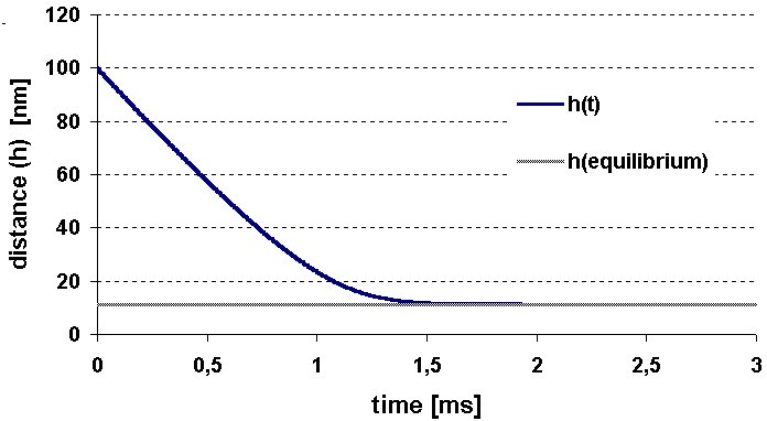
The results of calculations for our first generation model is shown in Fig. 3. One can see that the particle approaches the calculated value of equilibrium distance without crossing equilibrium distance line. Hence, the “dynamic critical distance” does not exist, in contrast to the hypothesis of Stefanescu et al [33, 36, 38, 44]. Therefore, the critical distance of engulfment should be calculated from the solidification front instability criterion. This criterion is included in our 2nd generation model, presented below.
Fig. 2. Stability analysis of the numerical solution (Ftotal º S F = Fi + Fd)
Fig.3. The change of the particle-front distance as a function of time
3. The Description of our Second Generation Model and Results The dynamic model of the 2nd generation is based on the steady-state model developed recently by Kaptay [46]. In this model the local curvature of the interface (Ri ) is considered behind the particle (see Fig.4). The relative curvature (a =R/ Ri) is calculated from the equilibrium between the Laplace pressure and the disjoining pressure [46] as:
The modified equations for the forces acting on the particle can be written with taking into account the effect of a as [46]:
Fig.4. Schematics of our second generation model with the curvature of the interface
The steady state is characterized by the balance of forces (see Eq.(3)). The critical velocity and critical distance has been found after some simplifications (a << h, R>> h) [46] at:
Using parameters listed in Table 1, the steady-state solution Eq-s (9.b-9.c) provides the following values for the critical parameters: vcr = 68.5 m m/s, hcr = 13.1 nm. Substituting Eq-s (1b, 2b, 6) into Eq.(5), the following modified equation can be obtained:
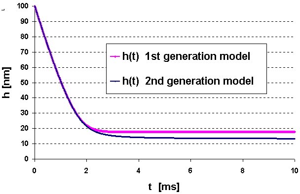
The constants A and B are described by Eq-s (7.a – 7.b). The values of parameters given in Table 1 and the starting conditions used in our first generation model have not been modified. In Fig.5 the results of calculations with the 2 models are presented, using identical parameters. Although both curves have reached the equilibrium distance, where the steady state appears, this distance is somewhat smaller in case of the 2nd generation model. While the equilibrium distance is 17.79 nm according to the 1st generation model, it becomes 13.41 nm, according to the 2nd generation model.
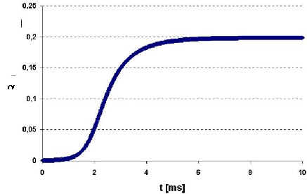
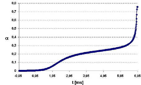
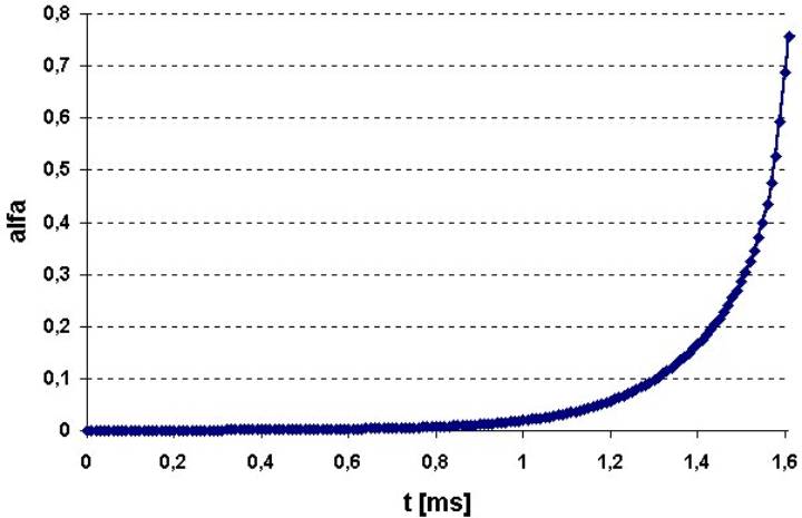
Fig.5 The particle-front distance h as a function of time (h0=100 nm, vi=65 m m/ s), according the two models used in this paper The main difference in the two models is, however, not in the slight difference in the equilibrium distances. The main difference can be seen, if the change of parameter a as function of time is shown for different interface velocity values, around the critical interface velocity (see Fig-s 6). The following conclusions can be made from Fig-s 6:
Summarizing Fig-s 6, the following conclusions can be made:
Fig.6. Parameter a as a function of time (parameters given in Table 1) vi= 65.000, 65.486 and 70.00 m m/s respectively for the top, middle and bottom figure
Conclusions
Acknowledgement The author thanks G.Kaptay and K.K.Kelemen of the University of Miskolc for their discussions during this work.
References 1. D.R.Uhlmann, B.Chalmers, K.A.Jackson, J. of Appl. Phys., 35 (1964) 2986-93. 2. G.F.Bolling, J.Cissé, J.of Crystal Growth, 10 (1971) 56-66. 3. A.W.Neumann, J.Székely, E.J.Rabenda, J. of Coll. & Interf. Sci., 43 (1973) 727-32. 4. A.M.Zubkov, V.G.Lobanov, V.V.Nikanova, Sov.Phys.Crystall, 18 (1973) 239-242. 5. A.A.Chernov, D.E.Temkin, A.M.Mel'nikova, Sov.Phys.Crystall, 21 (1976) 369-373. 6. D.E.Temkin, A.A.Chernov, A.M.Mel'nikova, Sov.Phys.Crystall, 22 (1977) 13-17, 656-8. 7. A.A.Chernov, D.E.Temkin, in: “Crystal Growth and Materials”, ed. by E.Kaldis and H.J.Scheel, , North Holland Publishing Co., Amsterdam, 1977, pp.3-77. 8. A.A.Chernov, V.L.Bronstein, Sov.Phys.Crystallogr, 23 (1978) 4-8. 9. M.K.Surappa, P.K.Rohatgi, J.Mater.Sci.Lett., 16 (1981) 765-772. 10. Ch.Körber, G.Rau, M.D.Cosman, E.G.Cravalho, J.of Crystal Growth, 72 (1985) 649-62. 11. D.M.Stefanescu, B.K.Dhindaw, S.A.Kacar, A.Moitra, Met.Trans., 19A (1988) 2847-55. 12. J.Pötschke, V.Rogge, J. of Crystal Growth, 94 (1989) 726-38. 13. R.Sasikumar, T.R.Ramamohan, B.C.Pai, Acta Metall., 37 (1989) 2085-91. 14. D.M.Stefanescu, A.Moitra, A.S.Kacar, B.K.Dhindaw, Met.Trans., 21A (1990) 231-39. 15. R.Sasikumar, M.Kumar, Acta Metall. Mater., 39 (1991) 2503-08. 16. D.Shangguan, S.Ahuja, D.M.Stefanescu, Met. Trans., 23A (1992) 669-80. 17. R.P.Smith, D.Li, D.W.Francis, J.Chappuis, A.W.Neumann, J. of Colloid and Interface Science, 157 (1993) 478-84. 18. S.Ahuja, D.M.Stefanescu, B.K.Dhindaw, in: “Proc. of 2nd Int. Conf. on Cast Metal Matrix Composites”, ed. by D.M.Stefanescu and S.Sen, 1993, pp. 44-56. 19. K.Mukai, W.Lin, Tetsu-to-Hagane, 80 (1994) 527-32. 20. K.Mukai, W.Lin, Tetsu-to-Hagane, 80 (1994) 533-38. 21. K.Mukai, W.Lin, in: “Proc. Int. Conf. High-Temperature Capillarity”, ed. by N.Eustathopoulos, Bratislava, 1995, 391-95. 22. Q.Han, J.D.Hunt, ISIJ International, 35 (1995) 693-99. 23. D.M.Stefanescu, R.V.Phalnikar, H.Pang, S.Ahuja, B.K.Dhindaw, ISIJ International, 35 (1995) 700-707. 24. G.Kaptay, Materials Science Forum, 215-216 (1996) 467-474. 25. K.Mukai, Tetsu-to-Hagane, 82 (1996) 8-14. 26. F.R.Juretzko, D.M.Stefanescu, B.K.Dhindaw, S.Sen, in: “Processing, Properties and Applications of Cast Metal Matrixc Composites”, ed. by P.K.Rohatgi, TMS, 1996, 21-31. 27. S.Sen, B.K.Dhindaw, D.M.Stefanescu, A.Catalina, P.A.Curreri, J.Cryst.Growth, 173 (1997) 574-84. 28. U.Hecht, S.Rex, Metall. Mater. Trans., 28A (1997) 867-74. 29. S.Sen, W.F.Kaukler, P.Curreri, D.M.Stefanescu, Metall. Mater. Trans., 28A (1997) 2129-35. 30. H.Nakae, S.Wu, Key Engineering Materials, 127-131 (1997) 503-510. 31. H.Nakae, S.Wu, Materials Science & Engineering, A252 (1998) 232-238. 32. H.Shibata, H.Yin, S.Yoshinaga, T.Emi, M.Suzuki, ISIJ International, 38 (1998) 149-56. 33. D.M.Stefanescu, A.V.Catalina, ISIJ International, 38 (1998) 503-505. 34. G.Kaptay, in: “Proc. of HTC 97”, ed. by N.Eustathopoulos and N.Sobczak, Foundry Research Institute, Cracow, Poland, 1998, pp. 388-393. 35. J.K.Kim, P.K.Rohatgi, Metall. Mater. Trans., 29A (1998) 351-358 36. D.M.Stefanescu, F.R.Juretzko, B.K.Dhindaw, A.Catalina, S.Sen, P.A.Curreri: Metall. Mater. Trans., 29A (1998) 1697-1706. 37. G.Kaptay, Metall. Mater. Trans., 30A (1999) 1887-1890. 38. D.M.Stefanescu, F.R.Juretzko, B.K.Dhindaw, A.Catalina, S.Sen, P.A.Curreri, Metall. Mater. Trans., 30A, 1999, 1890-1894. 39. G.Kaptay, Materials Science Forum, 329-330 (2000) 121-126. 40. S.Kimura, Y.Nabeshima, K.Nakajima, S.Mizoguchi, Metall. Mater. Trans., 31B (2000), 1013-1021. 41. S.Mukherjee, D.M.Stefanescu, in: “State of the Art in Cast MMCs, ed. by P.K.Rohatgi, TMS, 2000, 89-100 42. L.Hadji, in: “State of the Art in Cast MMCs, ed. by P.K.Rohatgi, TMS, 2000, 101-114 43. G.Kaptay, Metall. Mater. Trans., 31A (2000) 1695 – 1700. 44. D.M.Stefanescu, F.R.Juretzko, A.Catalina, B.K.Dhindaw, S.Sen, P.A.Curreri, Metall. Mater. Trans., 31A (2000) 1700 – 1705 45. A.V.Catalina, S.Mukherjee, D.M.Stefanescu, Metall. Mater. Trans, 31A (2000) 2559-2568. 46. G.Kaptay, Metall. Mater. Trans., 32A (2001) 993-1006. 47. Á.Borsik, K.K.Kelemen, G.Kaptay, Archives of Mechanical Technology and Automatization, 21 (2001) 19-28. 48. R.Asthana, P.K.Rohatgi, S.N.Tewari: in “Microstructure Formation during solidification of metal matrix composites”, ed. by P.K.Rohatgi, TMS, 1993, pp.11-28. 49. A.Mortensen, I.Jin, Int. Mat. Rev., 37 (1992) 101-128 50. R.Asthana, S.N.Tewari, J. of Materials Science, 28 (1993) 5414-25. 51. R.Asthana, S.N.Tewari, Composite Manufacturing, 4 (1993) 3-25. 52. Q.F.Li, D.G.McCartney, J. of Materials Processing Techn., 41 (1994) 249-62. 53. P.K.Rohatgi, K.Pasciak, C.S.Narendranath, S.Ray, A.Sachdev, J. of Materials Science, 29 (1994) 5357-66. 54. R.Asthana, J. of Materials Science, 33 (1998) 1679-1698 55. R.Asthana, J. of Materials Science, 33 (1998) 1959-1980. 56. Z.Wang, K.Mukai, I.J.Lee, ISIJ International, 39 (1999) 553-562. 57. G.Kaptay, K.K.Kelemen, ISIJ International, 41 (2001) 305-307. 58. K.Mukai, Z.Wang, W.Lin, ISIJ International, 41 (2001) 308-310. 59. H.A.Lorentz, Abh.theoret.Phys., 1 (1907) 23-57. 60. H.Brenner, Chem.Eng.Sci., 16 (1961) 242-51. 61.S.Yuu, Y.Fukui, AIChE Journal, 27 (1981)168-70. 62.G.Kaptay, K.K.Kelemen, in: “State of the Art in Cast MMCs, ed. by P.K.Rohatgi, TMS, 2000, 45-60. 63.P.G.Saffman, J.Fluid.Mech., 31 (1968) 624-30.
|
||||||||||||||||||||||||||||||||||||||||||||||
 (4)
(4) (4.a)
(4.a) (6)
(6) (7)
(7) (7.a)
(7.a) (7.b)
(7.b)
 (1.b)
(1.b)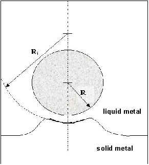
 (9.b)
(9.b) (9.c)
(9.c) (10)
(10)